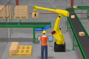
PLC eLearning Packages
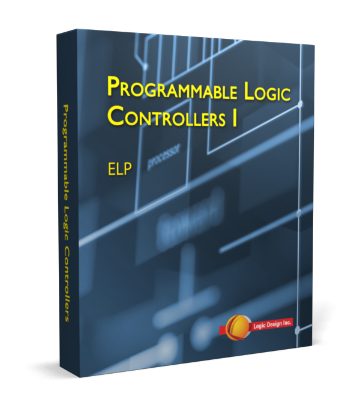
Ancillary learning materials for PLCLogix include eLearning Packages (eLPs) consisting of 19 modules of interactive curriculum using text, video, audio, 2D and 3D animations and PLCLogix simulation software. PLC eLP 1 uses PLCLogix 500, which emulates RSLogix 500, and provides a basic introduction to PLCs. PLC eLP 2 uses PLCLogix 5000, which emulates RSLogix 5000, and it is a more advanced study of PLCs in manufacturing. These multimedia programs include pre-tests, interactive exercises, and review questions. The eLPs include hundreds of pre-built laboratory exercises using PLCLogix 5000 or PLCLogix 500 that are integrated throughout the 19 modules.
The prices of the PLC eLPs are $445 and include a licensed copy of PLCLogix 5000 or PLCLogix 500. The eLPs are available as a Download which is compatible with any recent Windows-based operating system.
The following links provide you with detailed descriptions of the modules contained in the Programmable Logic Controllers eLPs.
-
1. Overview of PLCs
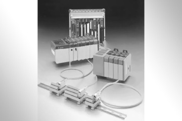
This module provides a general overview of PLCs and their application in industry. The origins of the PLC and its evolution are covered in detail. The advantages of PLCs are also outlined, and the main components associated with PLC systems are explored. An introduction to ladder logic is presented and the most common types of PLC signals are covered with an emphasis on practical application.
Learning Outcomes:
- Describe the purpose of a control panel
- Define a programmable logic controller
- List six factors affecting the original design of PLCs
- Name three advantages of PLCs compared to relay logic systems
- List the three main components in a PLC system
- Understand the term ladder logic
- Describe the application of PLC signals
- Explain the difference between a bit and a word
-
2. Central Processing Unit
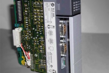
This module is intended to familiarize the student with the most important aspects of the PLC's central processing unit. Topics covered include memory devices and memory storage, as well as an introduction to data storage and processing. In addition to covering memory utilization and memory mapping, the module also provides detailed information on multiprocessing and PLC scan functions.
Learning Outcomes:
- Define the term CPU
- Explain the purpose of the executive program
- Understand the application of buses in a CPU
- List two types of CPU diagnostics
- Differentiate between fatal and non-fatal errors
- Explain the advantage of multiprocessing
- Describe the two general classes of memory devices
- Name four types of memory
- Define memory protect
- Explain the purpose of memory utilization and how it applies to PLC systems
- Describe the scan function
-
3. I/O System
This module covers all aspects of the Input/Output system for PLCs including discrete, analog, and data I/O. In addition, the module also presents an overview of I/O addressing and an introduction to I/O parameters. Module topics also include the principles of remote I/O and an introduction to scaling and resolution of analog devices and signals.
Learning Outcomes:
- Explain the purpose of the I/O system
- Describe how I/O addressing is accomplished
- Define discrete inputs
- List four tasks performed by an input module
- Describe the basic operation of a discrete output
- Explain the purpose of data I/O interfaces
- Describe the resolution of an analog I/O module
- List three applications for advanced I/O
- Explain the purpose of remote I/O

-
4. Programming Terminals and Peripherals
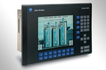
This module is intended to provide students with an overview of the wide range of programming terminals currently in use and to outline some of the key differences between them. In addition, the module covers topics such as hand-held programming terminals and computer-based software packages. The operation of host computer-based systems is also covered as well as the application of peripheral devices in a PLC network.
Learning Outcomes:
- Define the term programming terminal
- Describe the purpose of dedicated terminals
- List two types of programming terminals
- Describe the purpose of mini-programmers
- Define computer-based programming terminals
- Differentiate between programming software and documentation software
- Describe the operation of a host computer-based system
- Explain the purpose of peripheral devices
-
5. Installation and Maintenance of PLCs
The purpose of this module is to provide the student with a thorough coverage of the various safety precautions, preventative maintenance, and troubleshooting techniques associated with a typical PLC system. In addition, the module also covers proper grounding techniques, sources of electrical interference, and I/O installation techniques. Field checkout and troubleshooting is covered, with an emphasis on practical troubleshooting and problem-solving strategies.
Learning Outcomes:
- List three safety precautions when installing PLC systems
- Define system layout
- List three safety measures for PLC installations in control panels
- Describe proper grounding techniques for PLCs
- Name three precautions to avoid electrical interference
- Define cross-talk interference
- Explain I/O installation
- Describe the need for I/O documentation
- Define leakage current and explain the purpose of bleeder resistors
- Explain the field checkout of PLC systems
- Provide periodic maintenance for a PLC system
- Troubleshoot PLCs
- Describe redundant PLC architecture

-
6. Relay Logic
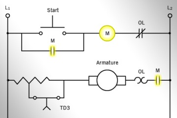
This module is intended to provide an introduction to relay logic and relay logic diagrams. The basic operating principles of relays are presented as well as detailed information regarding sizing and rating of electromagnetic contactors. Seal-in circuits and their application in control systems is discussed as well as an introduction to timing circuits. In addition, the module covers I/O devices and their application in PLC systems.
Learning Outcomes:
- Name three types of mechanical switches and three types of proximity switches
- Define inductive arcing and explain how it can be prevented
- Describe the basic operating principle of a control relay
- Explain the purpose of overload relays
- Define the term holding contact
- Differentiate between a control relay and a solenoid
- List three applications of rotary actuators
- Name three types of time delay relays
- Define the term relay logic
-
7. Ladder Logic
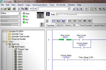
This module provides an introduction to ladder logic programming techniques using laboratory simulation software. The lab component of the module provides the student with an opportunity to write ladder logic programs and test their operation through PLC simulation. Topics covered in the module include I/O instructions, safety circuitry, programming restrictions and I/O addressing.
Learning Outcomes:
- Define ladder logic
- Explain the purpose of I/O addresses
- Describe the function of softwiring, branches, and rungs
- Write a ladder logic program
- Run a ladder logic program using lab simulator
- Define the terms examine on and examine off
- Explain the purpose of a latching relay instruction
- Differentiate between an internal output and an actual I/O output
- Describe the operation controller scan
- Name two programming restrictions
- Define nesting
- Explain why safety circuitry is important in ladder logic systems
- List three types of I/O addressing
-
8. Timers
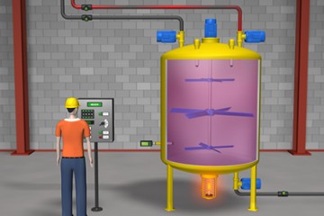
This module is intended to provide students with an overview of PLC timers and their application in industrial control circuits. Allen-Bradley timing functions such as TON, TOF, and RTO are discussed in detail and the theory is reinforced through lab projects using lab simulation software. In addition, students will learn practical programming techniques for timers including cascading and reciprocating timing circuits.
Learning Outcomes:
- Name two types of relay logic timers
- List the four basic types of PLC timers
- Describe the function of a time-driven circuit
- Differentiate between ON-delay and OFF-delay instructions
- Write a ladder logic program using timers
- Describe the operating principle of retentive timers
- Explain the purpose of cascading timers
- Define reciprocating timers
-
9. Counters
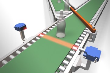
This module provides students with a broad overview of PLC counters and their application in control systems. Allen-Bradley counting functions such as CTU and CTD are presented in detail and the theory is reinforced through lab projects using lab simulation software. In addition, students will learn practical programming techniques for counters including cascading counters and combining counting and timing circuits.
Learning Outcomes:
- Name two types of mechanical counters
- Define the two basic types of PLC counters
- Write a ladder logic program using CTU, CTD and RES
- Explain the use of underflow and overflow
- Describe the function of an event-driven circuit
- Design an up/down counter
- Define cascading counters
- Explain the advantages of combining timers and counter
-
10. MCR, JUMP, and FORCE Instructions
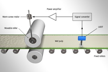
This module is intended to provide an overview of various zone control techniques and branching instructions. The principles of Master Control Relays are presented with an emphasis on safety considerations and compliance with safety codes and regulations. In addition, the module also provides coverage of subroutines and their application and benefit in complex control problems. Force instructions are presented and demonstrated through lab simulation software. The simulation software also allows the student to program and observe branching operations.
Learning Outcomes:
- Define master control relay
- Explain the purpose of a zone of control
- Describe the function of zone control latch
- Write a ladder logic program with a subroutine
- Describe the purpose of first failure annunciators
- Differentiate between a JSR and a JMP
- Explain the advantage of using subroutines
- Use the FORCE instruction for troubleshooting
-
11. Sequencers
This module is designed to provide the student with a clear understanding of the purpose and application of PLC sequencers, both through the theory of operation and through the actual demonstration using lab simulation software. The module will familiarize the learner with masking techniques and the various types of sequencers available including SQO and SQC instructions. In addition, sequencer charts are presented with an emphasis on maintenance and recording of sequencer chart information.
Learning Outcomes:
- Explain the operation of a mechanical drum controller
- Describe the basic function of a PLC sequencer
- Explain how time-driven sequencers operate
- Describe the operation of event-driven sequencers
- Derive a sequencer chart
- Define the term matrix
- Explain the purpose of masking
- List three types of sequencers
- Write a ladder logic program using SQO and SQC

-
12. Data Transfer
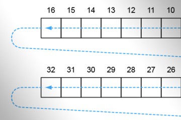
This module provides students with an introduction to the principles of data transfer, including bits, words, and arrays. Using lab simulation, various aspects of data transfer will be demonstrated and students will program and observe transfer instructions such as MOV. An introduction to shift registers is also presented with an emphasis on practical applications in industrial control circuits.
Learning Outcomes:
- Explain the purpose of a move instruction
- List three basic types of registers
- Define the term sign bit
- Explain the operating characteristics of a register-to-register move
- Differentiate between a file-to-word and a word-to-file move
- Describe the purpose of a table-to-table move
- Explain the operation of a shift register
- Write a ladder logic program using MOV
- Transfer data between memory locations
-
13. Math Functions
This module provides an overview of basic and advanced mathematical functions found in typical PLCs. It provides thorough coverage of data comparison instructions such as EQU, LES, and GRT. In addition, this module provides a foundation for more advanced programming techniques including analog input and output control. Topics such as combining math functions, averaging, scaling and ramping are presented with an emphasis on practical application and are demonstrated using lab simulation.
Learning Outcomes:
- List three types of data comparison
- Explain the Addition function
- Subtract two numbers using a PLC
- Multiply and divide two numbers
- Define the terms scaling and ramping
- Write a program using LES, GRT, EQU
- Use the Square Root instruction
- Write a program combining math functions
- Describe the purpose of LIM

-
14. Process Control
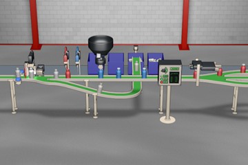
The purpose of this module is to provide the student with a thorough understanding of the various aspects of process control and its application to PLC systems. In addition to open-loop and closed-loop systems, the module also covers advanced closed loop techniques including PID control. Analog I/O devices are presented in detail and tuning parameters for PID control systems is demonstrated through practical examples.
Learning Outcomes:
- Define the terms process, process variable, and controlled variable
- Name four applications for control systems
- Explain the advantage of using block diagrams
- Describe the function of the setpoint, error signal, and measured value
- Differentiate between open-loop control and closed-loop control
- List the five basic components in a closed-loop control system
- Name the four variables associated with closed-loop control systems
- Define dead time
- Explain the basic principles of On-Off and PID control
- Describe the purpose of feedforward control in process systems
- Define the terms algorithm and flowchart
- Explain the basic principle of fuzzy logic
-
15. Data Communications
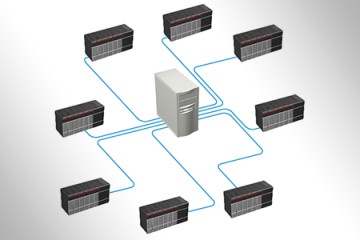
This module is intended to provide the student with an introduction to networking using PLC systems and peripherals. The principles of data highways are discussed using Windows platform and Rockwell hardware and programming software. In addition, an introduction to Ethernet and network switching is also presented as well as detailed descriptions of topology and the application of token passing in a data highway. The module also provides an overview of transmission media including fiber optic, coaxial, and twisted pair cable.
Learning Outcomes:
- Define the term data highway
- Describe the term protocol as it applies to PLC systems
- Explain the principle of token passing
- Name two types of topology
- List four factors affecting transmission media
- Describe the two types of bandwidth used in data highway systems
- Define response time
- Explain proprietary networks
- Describe the purpose of Manufacturing Automation Protocol (MAP)
- Name the seven MAP layers
- List three advantages of using Ethernet
- Explain the purpose of network switching
-
16. Number Systems and Codes
This module is designed to provide the student with a thorough understanding of the various number systems used by PLCs and their application in industrial control. The module covers binary numbers and codes including BCD, octal, and hexadecimal. In addition, the module also demonstrates through lab simulation how number systems are manipulated by the PLC's processor. Topics also covered in the module include negative binary numbers, parity bit, Gray code, and ASCII.
Learning Outcomes:
- Explain the operation of the binary number system
- Express a negative number in binary form
- Differentiate between least-significant and most-significant bit
- Add and subtract binary numbers
- Multiply and divide binary numbers
- Convert binary numbers to decimal, and decimal to binary
- Count using octal and hexadecimal number systems
- Write a program using number system conversion
- Differentiate between natural binary and Binary Coded Decimal (BCD)
- Describe the purpose of parity bit, Gray code and ASCII code

-
17. Digital Logic
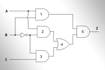
This module provides a thorough treatment of digital logic and its application in PLC programming and control. Boolean algebra and the theorems associated with it are presented and demonstrated through a series of programming examples. In addition, the student will become adept at converting digital logic to ladder logic and will apply DeMorgan's theorem to increase circuit efficiency and reduce redundancy.
Learning Outcomes:
- Apply truth tables to troubleshooting digital circuits
- List five logic gates
- Describe the basic operation of an inverter
- Explain the purpose of Boolean algebra
- Apply logic gate combinations to PLC control
- Convert digital logic to ladder logic
- Name eight Boolean theorems
- Apply DeMorgan's theorem to ladder logic circuits
-
18. RTUs & PACs
This module is designed to cover the fundamentals of Remote Terminal Units (RTUs) and Programmable Automation Controllers (PACs). The four types of connections used for interfacing with field devices are demonstrated, with an emphasis on practical application. A discussion of RTU architecture, communications and practical applications is presented. In addition, an overview of PACs and a comparison of PAC and RTU functionality is described and the differences between PLC and PACs are also highlighted. The main features of DNP3 protocols are introduced, and a discussion of alarm management and its application in RTUs and PACs is also included.
Learning Outcomes:
- Differentiate between an RTU and a PAC
- List the four types of RTU connections for interfacing to field devices
- Identify 7 specifications for selecting an RTU
- Define the communications protocol DNP3
- Describe the layers of the Enhanced Performance Architecture
- Name four common uses for RTUs in industrial applications
- Explain the main differences between RTUs and PLCs
- Define Alarm Management and explain its use in RTU systems
- Identify the five components in an Intelligent Electronic Device
- Name three differences between PACs and PLCs
- List the five main characteristics of a PAC

-
19. Introduction to Automation
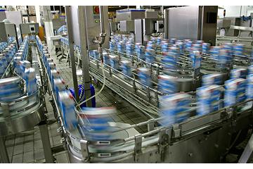
This module provides a general overview of automation systems and the role of automation in industry. It also covers the basic principles of flexible automation and flexible manufacturing systems. The advantages of automation are outlined, and the main components associated with automation systems are explored. An introduction to automation simulation is presented with an emphasis on practical application.
Learning Outcomes:
- Define the term automation
- List three advantages of using automation systems
- Name six factors affecting the original design of PLCs
- Describe the role of automation in industry
- Define flexible automation
- Differentiate between economy of scale and economy of scope
- List three examples of continuous flow processes
- Describe the purpose of a flexible manufacturing system
- Explain the difference between DCS, RCS and CCS
- Define automation simulation and explain its advantages
-
1. Introduction to Advanced PLCs
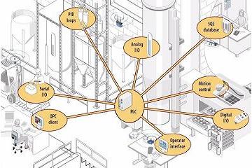
This module provides a general overview of the characteristics of advanced PLCs and their role in industry. The operation of deterministic systems and relational databases are described, and the advantages of using PLC languages based on the IEC-61131-3 standard are discussed. The differences between PLCs, PACs, and PCs are presented within the context of industrial automation and manufacturing. An introduction to tag-based addressing is presented, and the benefits of simulation of advanced PLCs are described.
Learning Outcomes:
- Name three characteristics of advanced PLCs
- Describe the purpose of a relational database
- Differentiate between scan times and ISRs
- Explain the operation of a deterministic system
- Describe the basic operation of a PAC
- List the main differences between a PLC and a PAC
- Name the four PLC languages in the IEC-61131-3 standard
- Differentiate between address-based and tag-based PLCs
- Explain the purpose of a controller organizer
- List three benefits of PLC simulation
-
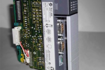
2. PLC Processors
This module is intended to familiarize the student with the most important aspects of the PLC's central processing unit with a focus on the ControlLogix processor. Topics covered in the module include memory devices, memory storage, and data processing as well as an introduction to tag-based memory. In addition to covering memory utilization and protection, the module also provides detailed information on multiprocessing and PLC scan functions.
Learning Outcomes:
- Explain the difference between a CPU and a MPU
- Name the four basic functions of a CPU
- Differentiate between volatile and nonvolatile memory
- Define flash memory
- Describe the main purpose of the scan cycle in a PLC
- Name two types of PLC memory protection
- List the major features of ControlLogix controllers
-
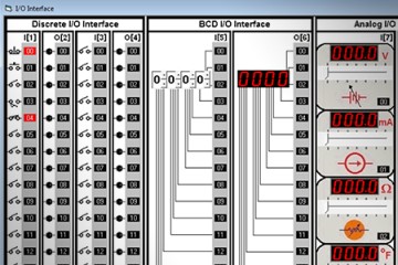
3. I/O System
This module covers all aspects of the Input/Output system for PLCs including discrete, analog, and data I/O. In addition, the module also presents an overview of I/O addressing and an introduction to I/O parameters. Module topics also include the principles of remote I/O and an introduction to scaling and resolution of analog devices and signals.
Learning Outcomes:
- Explain the purpose of the I/O system
- Describe how I/O addressing is accomplished
- Define discrete inputs
- List four tasks performed by an input module
- Describe the basic operation of a discrete output
- Explain the purpose of data I/O interfaces
- Define analog I/O
- Describe the resolution of an analog I/O module
-
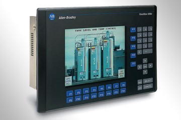
4. Programming Terminals and Peripherals
This module is intended to provide students with an overview of the wide range of programming terminals currently in use and to outline some of the key differences between them. In addition, the module covers topics such as hand-held programming terminals and computer-based software packages. The operation of host computer-based systems is also covered as well as the application of peripheral devices in a PLC network.
Learning Outcomes:
- Define the term programming terminal
- Describe the purpose of dedicated programming terminals
- List two types of programming terminals
- Describe the purpose of mini-programmers
- Define computer-based programming terminals
- Differentiate between programming software and documentation software
- Describe the function of a host computer-based PLC system
- Explain the purpose of peripheral devices
-
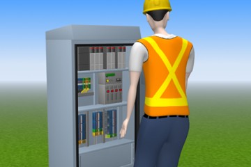
5. Installation and Maintenance of PLCs
The purpose of this module is to provide the student with a thorough coverage of the various safety precautions, preventative maintenance, and troubleshooting techniques associated with a typical PLC system. In addition, the module also covers proper grounding techniques, sources of electrical interference, and I/O installation techniques. Field checkout and troubleshooting is covered, with an emphasis on practical troubleshooting and problem-solving strategies.
Learning Outcomes:
- List three safety precautions when installing PLCs
- Define system layout
- List three safety measures for PLC installations in control panels
- Describe proper grounding techniques for PLCs
- Name three precautions to avoid electrical interference
- Define cross-talk interference
- Explain the principles of I/O installation
- Describe the need for I/O documentation
- Define leakage current and explain the purpose of bleeder resistors
- Explain the field checkout of PLC systems
- Provide periodic maintenance for a PLC system
- Troubleshoot PLCs
- Describe redundant PLC architecture
-
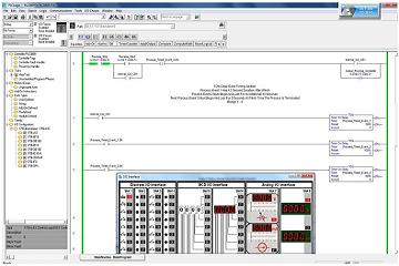
6. Tag-Based PLCs
This module introduces the student to the fundamentals of tags and tag-based PLC programming. In addition to produced and consumed tags, the module also covers common methods for creating tags and explains the purpose of User Defined Data Types (UDTs). Theoretical areas of study include continuous and periodic tasks as well as the various types of data used in tag-based I/O systems. The principles of projects, arrays, throughput, and scope are described in detail, emphasizing practical applications and standard programming techniques.
Learning Outcomes:
- Differentiate between address-based and tag-based PLCs
- Describe the main elements of a tag
- Define the term scope and explain its purpose in a tag
- List three methods for creating a tag
- Explain the purpose of a User Defined Data Type (UDT)
- Name three types of arrays
- Define Produced and Consumed tags
- Differentiate between a continuous task and periodic task
- Explain the principles of Logix5000 I/O addressing
- Describe the four types of data used in tag-based I/O
- List three methods to increase throughput
-
7. Ladder Logic Programming
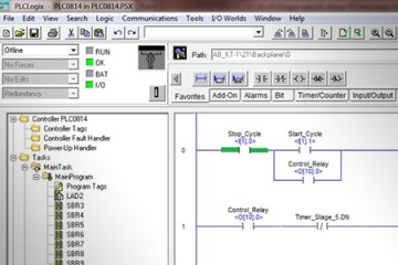
This module provides an introduction to ladder logic programming techniques using laboratory simulation software. The lab component of the module provides the student with an opportunity to write ladder logic programs and test their operation through PLC simulation. Topics covered in the module include I/O instructions, safety circuitry, programming restrictions, I/O addressing, FORCE instructions and bit status flags.
Learning Outcomes:
- Define ladder logic
- Convert relay logic schematics to ladder logic
- Write a ladder logic program using PLCLogix
- Define the terms examine on and examine off
- Explain the purpose of a latching relay instruction
- Differentiate between a branch and a nested branch
- Describe the controller scan operation
- Name two programming restrictions
- Describe the use of Force instructions in PLC applications
- Explain the purpose of bit status flags
-
8. Timers
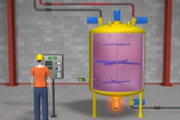
This module is intended to provide students with an overview of PLC timers and their application in industrial control circuits. PLC timing functions such as TON, TOF, and RTO are discussed in detail and the theory is reinforced through lab projects using lab simulation software. In addition, students will learn practical programming techniques for timers including cascading and reciprocating timing circuits.
Learning Outcomes:
- Name two types of relay logic timers
- List the four basic types of PLC timers
- Describe the function of a time-driven circuit
- Differentiate between ON-delay and OFF-delay instructions
- Write a ladder logic program using timers
- Describe the operating principle of retentive timers
- Explain the purpose of cascading timers
- Define reciprocating timers
-
9. Counters
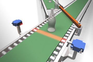
This module provides students with a broad overview of PLC counters and their application in control systems. PLC counting functions such as CTU and CTD are presented in detail and the theory is reinforced through lab projects using lab simulation software. In addition, students will learn practical programming techniques for counters, including cascading counters and combining counting and timing circuits.
Learning Outcomes:
- Name two types of mechanical counters
- Define the two basic types of PLC counters
- Write a ladder logic program using CTU, CTD and RES
- Explain the terms underflow and overflow
- Describe the function of an event-driven circuit
- Design an up/down counter
- Define cascading counters
- Explain the advantages of combining timers and counters
-
10. Branch and Loop Control
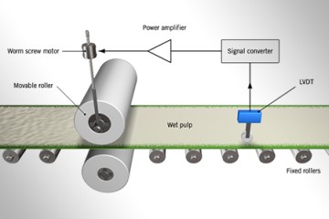
This module is intended to provide an overview of various branch and loop instructions including MCR, JSR and JMP. The use of PLC simulation software in this module allows the student to program and observe branching operations and to perform troubleshooting tasks. The principles of fault routines are presented with an emphasis on safety considerations and compliance with safety codes and regulations. In addition, the module also provides coverage of subroutines and their application and benefit in complex control problems. Force instructions are presented and demonstrated using PLCLogix simulation software.
Learning Outcomes:
- Define program control instructions
- Differentiate between master control reset and master control relay
- Explain the purpose of a jump instruction
- Describe the basic operation of a subroutine
- Use a Force command for troubleshooting
- Differentiate between a JSR and a JMP
- Explain the purpose of fault routine
- List the values associated with a GSV instruction
-
11. Sequencers
This module is designed to provide the student with a clear understanding of the purpose and application of PLC sequencers, both through the theory of operation and through the actual demonstration using lab simulation software. The module will familiarize the learner with masking techniques and the various types of sequencers available, including SQO, SQL and SQI instructions. In addition, sequencer charts are presented with an emphasis on maintenance and recording of sequencer chart information.
Learning Outcomes:
- Explain the operation of a mechanical drum controller
- Describe the basic function of a PLC sequencer
- Explain how time-driven sequencers operate
- Describe the operation of event-driven sequencers
- Derive a sequencer chart
- Define the term matrix
- Explain the purpose of masking
- List three types of sequencers
- Write a ladder logic program using SQO, SQL and SQI

-
12. Data Handling
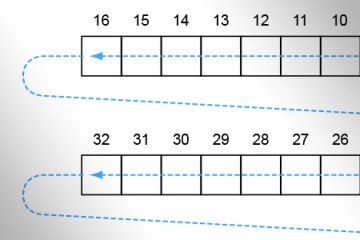
This module provides students with an introduction to the principles of Logix 5000 data handling, including bits, words, and arrays. Using PLCLogix simulation, various aspects of data transfer will be demonstrated and students will program and observe transfer instructions such as MOV, FFL and LFU. An introduction to shift registers is also presented with an emphasis on practical applications in industrial control circuits.
Learning Outcomes:
- Name the three main data handling functions
- Differentiate between words and arrays
- Convert data from one form to another
- Explain the purpose of a move instruction
- Write a ladder logic program using an MOV instruction
- Describe the purpose of an array-to-array move
- Name two types of shift registers
- Differentiate between FIFO and LIFO instructions
- Transfer data between memory locations
-
13. Math Instructions
This module provides an overview of basic and advanced mathematical functions found in the Logix 5000 PLC. It provides thorough coverage of data comparison instructions such as EQU, LES, and GRT. In addition, this module provides a foundation for more advanced programming techniques including analog input and output control. Topics such as combining math functions, averaging, scaling and ramping are presented with an emphasis on practical application and are demonstrated using PLCLogix lab simulation.
Learning Outcomes:
- Name the four main PLC mathematical functions
- List three types of data comparison
- Add and subtract numbers using PLC instructions
- Write a ladder logic program using MUL and DIV instructions
- Define the terms scaling and ramping
- Use LES, GRT, and EQU instructions in a ladder logic program
- Write a program using the SQR instruction
- List three advanced math operations
- Describe the purpose of an AVE instruction

-
14. Process Control
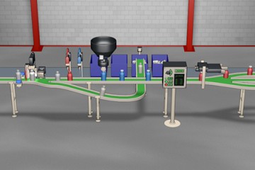
In this module, the student learns the principles of industrial control systems including open- and closed-loop control. Proportional, Integral, and Derivative control are covered with an emphasis on practical application and design. An introduction to algorithms and flow charts is also presented.
Learning Outcomes:
- Define the terms process, process variable, and controlled variable
- Name four applications for control systems
- Explain the advantage of using block diagrams
- Describe the relationship between the setpoint, error signal, and measured value
- Differentiate between open-loop control and closed-loop control
- List the five basic components in a closed-loop control system
- Name the four variables that are generally used to evaluate the performance of a closed-loop control system
- Define dead time
- Explain the basic operating principles of on off, proportional, integral, derivative and PID control
- Describe the purpose of feedforward control in process systems
-
15. PLC Communications
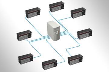
This module is intended to provide the student with an introduction to data communication using PLC systems and peripherals. The fundamentals of LANs and data highways are discussed using Windows platform and Rockwell hardware and programming software such as RSLinx. In addition, an introduction to Ethernet and network switching is also presented, as well as detailed descriptions of topology and the operation of token passing in a data highway. The module also provides an overview of transmission media, response time and the basic principles of proprietary networks, including the seven MAP layers.
Learning Outcomes:
- Define the term data communication
- Explain the purpose of a LAN
- Describe the term protocol and its application to PLCs
- Differentiate between OLE and DDE
- Name two types of topology
- List four factors affecting transmission media
- Define the term response time
- Describe the basic principles of proprietary networks
- Name the seven MAP layers
- List three advantages of using Ethernet
- Explain the purpose of network switching
- Name three types of RSLinx diagnostic resources
-
16. Distributed Control Systems (DCS)
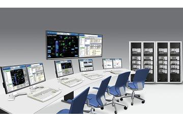
This module is intended to familiarize the student with the most important aspects of Distributed Control Systems. Topics covered in the module include remote terminal units (RTUs), HMIs and an introduction to LANs. The student will also learn the differences between star, bus and ring topology and their applications in automation systems. In addition to covering system architecture and algorithms, the module also provides detailed information on practical applications for DCS. Emphasis is placed on design, problem solving and analysis of industrial automation systems.
Learning Outcomes:
- Differentiate between DCS and SCADA
- List the three main elements in a DCS
- Identify the difference between uptime and system latency
- Explain the purpose of a remote terminal unit (RTU)
- Define task architecture and hardware architecture
- Describe the reason why algorithms are popular in DCS
- Name four common uses for HMI in DCS applications
- Explain the function of a local area network (LAN)
- Identify three components of quality of use in HMI
- Define the terms topology and Ethernet
- Compare software-based alarms with hardware-based alarms
- List five applications for DCS
- Name the four elements in a typical OTS
-
17. SCADA Systems
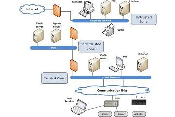
This module is intended to provide the student with an introduction to SCADA using automation systems and peripherals. The principles of alarm management are presented along with an overview of the alarm management lifecycle and an introduction to Six Sigma. SCADA security and authentication methodologies are also discussed in detail. Practical examples of SCADA applications are presented and include a discussion of SCADA simulation techniques.
Learning Outcomes:
- Describe the basic function of a SCADA system
- List four examples of SCADA systems
- Define SCADA architecture
- Identify seven elements in a SCADA system
- Explain the purpose of alarm management
- Identify three types of changes noted by alarms and events
- List the 10 stages of an alarm management lifecycle
- Describe how Six Sigma is applied to alarm management
- Explain the purpose of a firewall in a SCADA system
- Define the term SCADA security
- Name the two most common authentication methodologies
- Describe the benefits of SCADA simulation
-
18. Advanced PLC Programming Languages
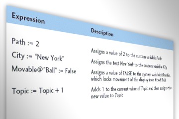
This module provides students with an introduction to advanced PLC programming languages which are widely used in industrial automation. In addition to graphical languages such as Sequential Function Chart (SFC) and Function Block Diagram (FBD), text-based languages such as Structured Text (ST) and Instruction List (IL) are also presented. Numerous programming examples are discussed using real-world applications and problem-solving techniques. This module also provides an overview of the RSLogix 5000 programming language and controller organizer, including tagnames, alias tags, and various editors (ST, FBD, SFC, etc.)
Learning Outcomes:
- Explain the purpose of the IEC61131-3 programming standard and its application in industry
- Name two text-based languages and three graphical languages
- Describe the basic programming and operating characteristics of Sequential Function Chart (SFC)
- List the three main parts of a function and explain their application in Function Block Diagrams (FBD)
- Write a simple Structured Text (ST) program
- Differentiate between Instruction List (IL) programming and ST
- Define online editing
- Describe the function of program tags in the RSLogix 5000 software
- List the four programming languages used by RSLogix 5000
- Explain the purpose of the Controller Organizer in RSLogix 5000
-
19. Robotics
This module provides an in-depth look at the industrial robot and the role it plays in industrial manufacturing processes. The origins of the industrial robot and its evolution are described. The types, components, accuracy, programming and applications of robots, among other topics, are thoroughly analyzed. Robot sensors, including vision and tactile detection are covered with an emphasis on practical application. This module also provides an overview of safety considerations including fail-safe operation and work-envelope design. The concept of Artificial Intelligence and how it relates to industrial machines is presented in detail.
Learning Outcomes:
- Define a robot
- Name the three general classifications of robots
- Describe the basic principle of a teach pendant
- Differentiate between a control system and a manipulator
- List the degrees of freedom for a four-axis robot
- Differentiate between pitch, yaw, and roll
- Define the term work envelope
- Name the three basic coordinate systems
- Explain the main differences between PUMA and SCARA robots
- Define payload, repeatability, and accuracy
- List five functions performed by vision and touch sensors
- Explain how collision protection provides for human safety
- Name six applications for industrial robots
- Define artificial intelligence